In The Race For Space, It Was Not Always The U.S. Against The Russians, Sometimes It Was NASA Against The Air Force In The Curious Case Of The Forgotten Lifting Bodies!
By Terry L. Sunday, in the August 1985 edition of Wings
 Martin Marietta’s X-24A was the last of three distinctly different lifting body designs to be flight tested, lagging by some three years the earlier Northrop M2-F2 and HL-1 O. While the M2 series (the M2-F1, M2-F2 and M2-F3) and the HL-10 were developed strictly as NASA research aircraft, the X-24A began life as a U.S. Air Force program, its genesis so complicated by politics and intra-government squabbles that at times it was doubtful it would ever fly. The X-24A program grew from the eventual merging of two parallel sets of events — the development of lifting body technology, and the often-stymied efforts of the Air Force to create a military manned spaceflight program. First, a look at the X-24A’s forerunners.
Predecessors of the X-24A
Lifting bodies are wingless flight vehicles that obtain lift from carefully contoured body shapes rather than from conventional wings. The idea was first conceived in 1957 by Dr. Alfred J. Eggers, then Assistant Director for Research and Development Analysis at Ames Research Center, California. Even though at the time the first U.S. satellite had not yet been launched, the various NACA (National Advisory Committee for Aeronautics) research centers and the military services, primarily the Air Force, had plenty of plans, schemes and proposals for serious spaceflight programs. The lifting body concept seemed an attractive design approach for a manned spacecraft. Such a vehicle could be boosted into orbit, make a few circuits to accomplish its mission, then reenter the atmosphere and land on a runway like a conventional aircraft. The lack of wings simplified structural design and minimized reentry heating problems, and the ability to land at nearly any airbase within a large maneuverability “footprint” provided a lot of operational flexibility. The inherent reusability of such vehicles would also keep mission costs down.
To find out whether the concept was workable, Ames designed the M2-F1, a twenty-foot cargo plane long, 1,140-pound half-cone lifting body. The Sailplane Corporation of American built the vehicle to Ames’ specifications from mahogany plywood and welded steel tubing, and by early 1963 it was ready for flight tests at Edwards Air Force Base, California. After a series of towed flights behind, first, a souped-up Pontiac convertible, and later a C-47 cargo plane, the first free flight was made on August 16, 1963, with NASA research pilot Milton O. Thompson at the controls. Cutting loose from the tow plane at 10,000 feet, he brought the M2-F1 in for a smooth landing on Rogers Dry Lake after an uneventful two-minute flight. Between 1963 and 1964, the M2-F1 was flown more than 100 times by NASA and Air Force pilots, including Chuck Yeager, then Chief of the Air Force Test Pilot School, who took a familiarization flight in the craft. The flights revealed a few handling deficiencies, mainly poor lateral stability compared to standard aircraft. Still, NASA was very encouraged by the results, and in June 1964, after evaluating proposals submitted by General Dynamics, North American Aviation, Northrop, Ryan Aeronautical and United Technology Center, contracted with Northrop Aircraft Corporation’s Norair Division to build two all-metal “heavyweight” lifting bodies. These were intended to gather design and handling qualities data for follow-on hypersonic aircraft and reentry vehicles.
The first Northrop lifting body was the M2-F2, a scaled-up (5,880 pounds empty weight) version of the M2-F1. The other, based on a NASA Langley Research Center design, was the 4,900-pound HL-10. The two aircraft differed considerably from each other in external shape, but internally they were nearly identical, an approach Northrop utilized to keep program costs down. NASA was very budget-conscious at the time because of its enormous expenditures on the Apollo moon program, and this kept its lifting body efforts austere. The M2-F2 was a blunted half-cone, flat on the top and rounded on the bottom, while the HL-10 — resembling an upside-down airfoil when seen from the side — was flat on the bottom and rounded on the top. The HL-10 was shaped for optimum trim at Mach 10+, but it was never intended to approach such speeds during its test program, for it lacked both the power and the thermal production required.
[hr4]
Northrop NASA Lifting Body Tests HL-10, M2-F2, M2-F3, via AirBoyd.TV
[hr4]
Each vehicle would be carried aloft under the right wing of the same Boeing NB-52 that was used for X-15 launches. An adapter was fitted to the standard X-15 pylon for lifting body flights — again, a cost-saving measure. Both M2-F2 and HL-10 were fitted with a single, four-chamber Thiokol Reaction Motors XLR-11 rocket engine of the same design used in the Bell Aircraft X-1, pioneer supersonic aircraft of nearly 20 years before. The test program plans included glide flights to evaluate subsonic handling characteristics and landing behavior, followed by transonic and supersonic flights under rocket power. By lighting from one to four chambers, the pilot could vary the thrust from 2,000 to 8,000 pounds and easily accelerate the blunt bodies to supersonic speeds.
The M2-F2 was rolled out at Northrop’s Hawthorne, California, plant on June 15, 1965, and was immediately shipped to Ames for full-scale wind tunnel testing. It was then transported to Edwards where, after a number of captive flights beneath the NB-52, its glide test program got started with the first free flight on July 12, 1966. Milt Thompson was the pilot. The unpowered test phase went very well for the first fifteen flights, and plans were being finalized for the first rocket test. Then, during the sixteenth flight on May 10,1967, while testing reduced roll and yaw damping gains in the flight control system, NASA research pilot Bruce Peterson was severely injured when the M2-F2 crashed on landing. Coming out of a turn onto the landing approach, the aircraft experienced lateral oscillations that became nearly uncontrollable, rolling through bank angles of up to 140 degrees at 200 degrees per second. Totally occupied with trying to stabilize the aircraft (which he did within 11 seconds), Peterson drifted off course nearly 1/2-mile to the left of the lakebed markings which were normally used for altitude cues during final approach. Worse, the M2-F2’s violent motions forced the chase plane pilots to move away to a safe distance, so they were not in position to provide the usual altitude callouts during the landing flare. As a result, the lifting body struck the lakebed before the landing gear was completely extended. It hit hard, bounced, rolled, somersaulted and finally came to rest upside down. Peterson was pulled out within minutes by the crew of a rescue helicopter that had been hovering near the landing area. (The scene that began each episode of the television program “The Six Million Dollar Man” was taken from tracking camera tapes of the M2-F2 accident.)
[hr4]
The Real Crash behind “The Six Million Dollar Man”
Test Pilot Bruce Peterson was on flight 16 of the M-2/F2, the previously unplanned last unpowered drop from the B-52 008 at 45,000 feet. A helicopter was believed to be in the wrong position and steering clear meant Peterson lost pre-flare airspeeded needed to bring the nose up to land. He put the nose down but entered a PIO (the rolling motion you see). He recovered but was too low to make it to the runway. He couldn’t judge distance and the landing gear was lowered just a second too late. For the record, he was generally headed south at the time, and barely missed the highway fence. The color cameras were set up where he had planned to land. Black & White long-range cameras were the only ones to record the crash, and the footage would become famous within only a few years on TV. Peterson never cared for “The Six Million Dollar Man” or the weekly replay of a crash that all too many at NASA blamed on “pilot error.” Many believe that the helicopter was truly in the wrong place, and that the accident could have been worse if Peterson would have struck it.[hr4]
Despite the severity of the crash, both pilot and aircraft flew again. After over 18 months of treatment, including a great deal of plastic surgery, Bruce Peterson was back in the air. Northrop rebuilt the M2-F2 into the M2-F3, adding a central fin and a reaction control system, but it didn’t fly again until June 2,1970, well after the X-24A program had started. The Northrop aircraft was removed from flying status in 1973, after 27 successful flights, and was retired to the National Air and Space Museum two years later. During its test program, the M2-F3 reached an altitude of 71,500 feet and a speed of over Mach 1.6.
The HL-10, rolled out on January 18, 1966, did not suffer any mishaps during its flight test program, which began with a glide flight by Bruce Peterson on December 22, 1966. However, insufficient lateral control authority was revealed on this flight, which grounded the HL-10 for some 15 months while fixes were identified, installed and wind-tunnel tested. The HL-10 took to the air for its second glide flight on March 15, 1968. After ten more glide flights, NASA research pilot John A. Manke became the first person to fly a lifting body under rocket power on November 13, 1968, (a powered flight was attempted by Air Force Major Jerauld R. Gentry on October 23, but engine problems caused a premature shutdown). Dropping from the NB-52 at 35,000 feet, Manke fired two of the XLR-11’s four chambers for 184 seconds, attaining an altitude of 42,650 feet and a speed of 524 miles per hour. Shortly after X-24A testing began at Edwards, Manke piloted the HL-10 to the first supersonic flight of a manned lifting body — Mach 1.13, or 744 miles per hour — on May 9, 1969. The 37th and last HL-10 flight took place on July 17, 1970, ending a test program that had seen the aircraft reach an altitude of over 90,000 feet and a speed of Mach 1.9. At that time, the X-24A had five powered flights to its credit and the M2-F3 program had just started.
[hr4]
HL-10 approach and landing at Edwards Air Force Base
[hr4]
The Air Force in Space
At about the same time the lifting body idea was first conceived, the Air Force also began efforts to establish a military manned spaceflight program. The National Aeronautics and Space Act (Public Law 85-568), signed into law by President Dwight D. Eisenhower in October 1958, created NASA as the national civilian space agency, and tacitly assigned it responsibility for the nation’s manned spaceflight efforts. Even though the services had manned spaceflight plans dating back to the early 1950s, NASA was now charged with carrying out the plans. Project Mercury, for example, was based on an Air Force study. The Air Force was quite miffed at NASA’s lead role, and for years afterward tried hard to sponsor and, more important, sell to the Congress and the President programs that would put the service in the manned spaceflight business.
The Air Force’s various manned orbital spacecraft concepts had crystallized by late 1957 into a vehicle known as “Dyna-Soar.” The name was a contraction of “dynamic soaring,” and alluded to the ability of the delta-winged craft to achieve a large landing footprint by gliding through the upper layers of the atmosphere during reentry from orbit. In April 1960, the Boeing Aircraft Company of Seattle, Washington, was selected to build two of the sinister looking black gliders, while the Glenn L. Martin Company, of Baltimore, Maryland, was tasked to adapt its Titan I Intercontinental Ballistic Missile (ICBM) to serve as the Dyna-Soar booster. Thus, while NASA worked the Mercury, Gemini and Apollo programs, the Air Force had in the Dyna-Soar, nominally a “research” vehicle, what it regarded as the precursor to a full-fledged military space program that it hoped would evolve by the end of the decade. These hopes would quickly be dashed.
[hr4][hr4]
By the end of 1963, just after the wooden M2-F1 started flying, the Air Force had spent more than $400 million on Dyna-Soar. Boeing had built a full-scale mockup (35 feet long with a 20-foot wingspan), and was working on the first prototype. Then, on December 10, Secretary of Defense Robert S. McNamara, the blue-pencil king, cancelled the program on the grounds that it was overly expensive and unnecessary. He had good reason. The major factor that doomed Dyna-Soar, other than its astronomical cost, was its lack of a well-defined military mission. The Air Force studied a wide variety of tasks that Dyna-Soar might perform, including reconnaissance, global bombing, crew and supply deliveries to a (nonexistent) space station, and many others, but none was sufficiently important to justify the estimated $1 billion that the program would cost to get the vehicle flying. (As a Dyna-Soar footnote, the Martin Titan booster design was upgraded and improved as Dyna-Soar weight and orbital requirements changed, and these efforts eventually led to the highly successful Titan III that still is the major Air Force expendable space booster today, and has also been used to launch interplanetary probes.)
To mollify the Air Force, severely stung by Dyna-Soar’s cancellation, the Department of Defense approved a new technology development effort in August 1964, just after NASA contracted with Northrop for the M2-F2 and HL-1 O. Known as the START program (Space Technology and Advanced Reentry Test), it was run by the Air Force Space Systems Division (SSD). START was divided into four phases, involving both unmanned reentry tests and manned low-speed research vehicles, and taken all together could still put the Air Force in the manned spaceflight business, albeit at a slow, measured pace. The first phase, ASSET (standing for Aerothermodynamic/elastic Structural Systems Environmental Tests), was already underway when START was authorized — it had begun in 1960 to support Dyna-Soar. ASSET involved six flights of small, unmanned, radiation-cooled refractory-metal reentry test vehicles fired down the Atlantic Missile Range by Douglas Thor boosters. These tests were conducted between 1963 and 1965. START’s second phase was called PRIME (Precision Recovery Including Maneuvering Entry), and this phase was directly related to the X-24A. The objective of the PRIME tests was to demonstrate the controlled, maneuvering reentry of an unmanned lifting body, using a reentry vehicle that was essentially a one-fourth-scale X-24A. START’s third phase, a manned lifting body effort to investigate the flight regime from about Mach 2 down to landing speeds, became the X-24A program, but in typical DoD fashion it needed an acronym — PILOT, standing for Piloted Low-speed Test. Finally, Phase 4, which never happened because of the funding drain of the Vietnam war and because other competing programs also required money, called for a manned orbital flight test of a reentry vehicle design based on the results of the other three phases.
 The Air Force wanted two manned SV-5s for PILOT, so that a serious accident need not bring the program to a standstill, but DoD eventually authorized only one. Even this was a triumph considering an early obstacle that nearly killed the program before it got started. In October 1964, Langley Research Center published NASA Technical Note TN X-981 , entitled “Stability and Control Characteristics of a Flat-Bottomed Lifting Reentry Configuration at Mach 1.6.” The report presented results of April 1963 wind tunnel tests on an early SV-5 configuration, and concluded that the design was unstable and “unsuitable for manned flight.” DoD promptly cancelled all references to the manned flight portion of START and cut off Fiscal 1966 funding for that part of the program. The Air Force’s SSD responded by pointing out that the current SV-5 was a substantially different design from the early one Langley had tested, and in fact was the best lifting body shape yet devised. Ultimately DoD was convinced and reinstated the manned flights, but only after a lengthy delay, and after authorizing the program, DoD stipulated that money and manpower expenditures be kept to a minimum.The Air Force’s interest in lifting bodies in late 1964 meshed nicely with NASA’s M2-F2 and HL-10 programs which were just getting underway at Northrop. The service and the civilian agency hammered out a joint flight test program that would give the Air Force pilots some stick time in the NASA aircraft. There was a precedent — NASA and the Air Force, as well as the Navy, had been cooperating on the X-15 program since 1954. However, when a vehicle was selected early in 1965 for START’s Phase 3, the Air Force was not about to choose a NASA design. Instead, the service turned to Martin Marietta. Formed in 1961 by the merger of the Glenn L. Martin Company and the American Marietta Corporation, the “Martin” side of Martin Marietta had devoted over two million man-hours to lifting body studies and analyses for over six years. One of the products was a sophisticated lifting body configuration called the SV-5.
Martin designed the SV-5, but in mid-1965 there was some question about who would build it. While the Air Force and NASA were defining detailed plans for their joint lifting body test program, Northrop — who had just rolled out the M2-F2 — offered to build the SV-5 from Martin’s plans for a fixed price of $1..5 million. This turned out to be considerably less than Martin’s proposed cost. It appeared for a while that this was the only way the SV-5 would ever fly, but finally Martin’s lobbying and price-reduction efforts, combined with the good working relationship formed with the Air Force over the years, kept the program in Baltimore. Martin was finally put under contract to build the SV-5 on March 2,1966 (six weeks after HL-10 rollout), but by then Air Force program responsibility had been transferred from SSD to the Aeronautical Systems Division (ASD), headquartered at Wright-Patterson Air Force Base, Ohio. This change in program management dimmed the prospects for a follow-on X-24A-based manned spacecraft, since SSD, the logical agency to handle such a program, was now out of the loop.
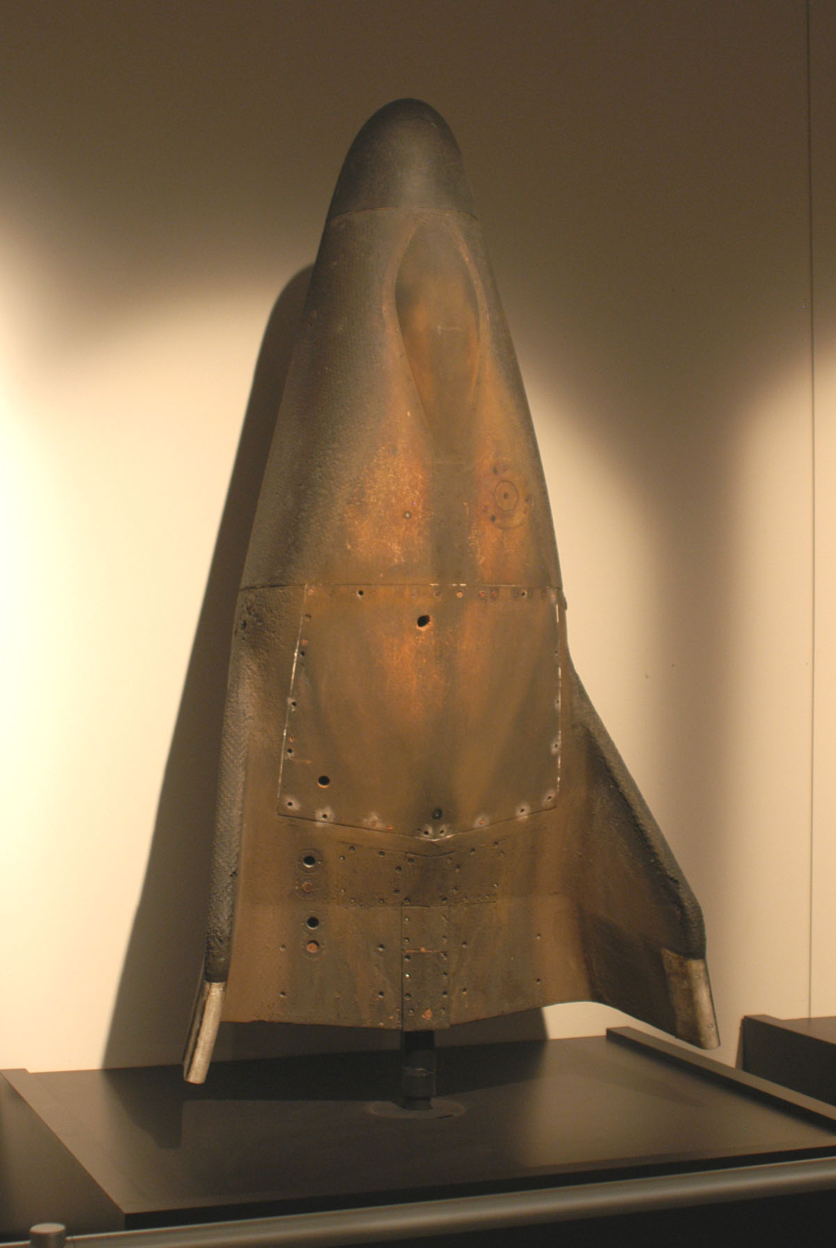
The basic SV-5 lifting body shape was eventually built in three incarnations — SV-5D, SV-5P and SV-5J. The SV-5D was the unmanned PRIME vehicle. Four were built, three were launched on suborbital reentry tests using General Dynamics / Convair Atlas boosters (on December 21,1966, and March 5 and April18, 1967). The first three tests were so successful that a planned fourth flight was cancelled. The SV-5P was the PILOT test vehicle, which on rollout was redesignated X-24A. Finally, the SV-5J was a jet-powered version intended to be a low-speed pilot trainer and configuration testbed. The SV-5J could take off under its own power, and so would not have to wait for the heavily scheduled NB-52 carrier aircraft, which was also being used for the M2-F2, HL-10 and X-15 programs. Test pilots could also shoot touch-and-go landings, a feat impossible with the other lifting bodies. Martin built two SV-5Js using company funds, and these were originally scheduled to precede the X-24A into the air by about two months. However, problems with insufficient thrust from their Pratt &Whitney J60-1 engines (Which were never installed in the airframes) kept them from ever flying. One of the reasons the Air Force originally contracted for the X-24A was because it seemed to offer a long-term opportunity for the service to develop a military manned spaceflight capability. With Dyna-Soar defunct, the Air Force had little choice if it wanted to have a foot in the door when future program opportunities arose. However, even before Martin cut the first metal it was pretty clear that the service’s hopes for the X-24A would not be realized. As an aerodynamic test vehicle, the X-24A, and even more so its successor the X-24B, provided invaluable data directly usable in the design of the Space Shuttle. But as a precursor to a military manned spacecraft, it was a dead end.
The X-24A Described
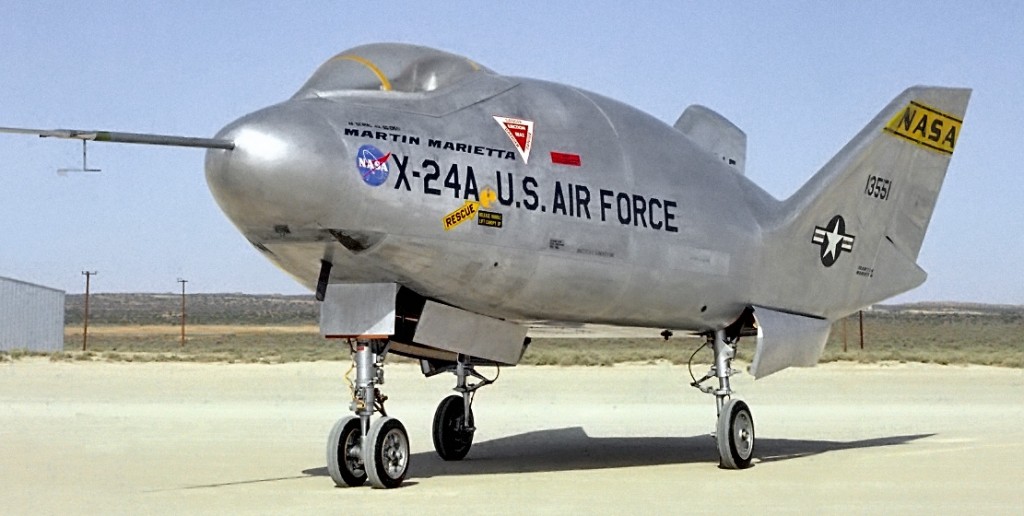
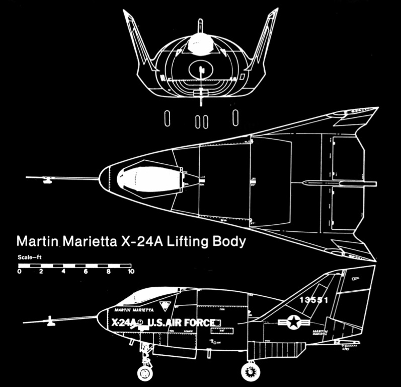
The aircraft that was rolled out of the assembly hangar at Martin’s Middle River plant on July 11, 1967, was called “flat-iron shape” in a company press release. Other observers called it a “finned potato.” Whatever the description, the X-24A, as it was officially designated that day, was the most advanced lift body yet built. • One of the figures used to describe lifting body performance is maximum lid, which is the ratio of lift to drag under certain conditions. The supersonic (or hypersonic) and subsonic lid ratios of the same vehicle can be quite different. For example, the M2-F2, a simple blunted cone, had a L/D of about 1.2 supersonically and 3.1 subsonically. The HL-10, a more sophisticated shape with its straight upper surface and curved bottom, had a supersonic II d of 1.3, and early predictions puts its subsonic lid in the 3.8-to-4.0 range. However, during flight tests it proved to be nearly the same as the M2-F2. The X-24A had the most refined shape of any of the lifting bodies. Like the HL-10, its bottom surface was gently cambered to optimize high-speed performance, giving it a supersonic lid of 1.4. Its unique highly-arched upper surface brought its subsonic lid up to about 4.5.
The X-24A was constructed of conventional materials, mainly aluminum, using standard aircraft techniques. The semimonocoque fuselage was 24 feet 6 inches long (almost 2Y2 feet longer than the M2-F2 and HL-1 a), and the span across the tips of the outward-canted fins was 13 feet 8 inches. Resting on its landing gear, the X-24A stood 10 feet 4 inches tall. Its empty weight was about 6,000 pounds, while a typical gross weight at launch was about 11,300 pounds.
To keep costs down, the X-24A was built with off-the-shelf hardware wherever possible. The rocket-propelled zero-zero ejection seat, slightly modified, was taken from a Convair F-1 06 Delta Dart. Northrop T-38 main landing gear was used, with nose gear from a North American T-39. All three lifting bodies used the same trainer landing gear design. The Air Force originally considered fixed or retractable skids instead of wheels for the X-24A, but finally decided to retain the system that worked successfully on the other two vehicles. Because the gear was not lowered until seconds before touchdown, and since wave-offs were impossible, fast-acting, reliable gear extension was essential. A one-shot pneumatic system blew the gear down, the main struts locking into place within 1.2 seconds, and the nose gear taking 1.5 seconds. The gear was manually retracted before each flight.
The X-24A XLR-11 -RM-13 rocket engine, serial number 008, was obtained from the X-15 program. Because of development delays with the X-15’s big, single-chamber XLR-99 engine, the first 24 X-15 powered flights were made using two XLR-11 engines. When the XLR-99 was finally delivered in May 1960, the X-15 program was left with five surplus XLR-11s. One was later installed in each of the three lifting bodies. The four-chamber, regeneratively cooled XLR-11 burned liquid oxygen (LOX) and a water/ethyl alcohol mixture (WALC). It was fed by turbopumps driven by a turbine that was in turn powered by a gas generator fueled with concentrated hydrogen peroxide. The main cylindrical propellant tanks carried up to 2,510 pounds of WALC and 2,670 pounds of LOX. Smaller tanks contained 4,200 psi helium gas to pressurize the main tanks and actuate the propulsion system valves, and 200 pounds of hydrogen peroxide for the turbopump gas generator. With all four chambers lit, about 1’37 seconds of burn time was available.
The X-24A, like the other two lifting bodies, was fitted with two throttle-able 500-pound-maximum-thrust “landing rockets,” one 3 nestled on either side of the four main chambers. The pilot could fire these to effectively increase lid and stretch out the landing flare if he found himself in a low-energy situation at low altitude. Fueled with hydrogen peroxide, they were adapted from the lift rockets developed for the Bell Aerosystems Lunar Landing Research Vehicle (LLRV) used to train Apollo astronauts in Lunar Module touchdown procedures.
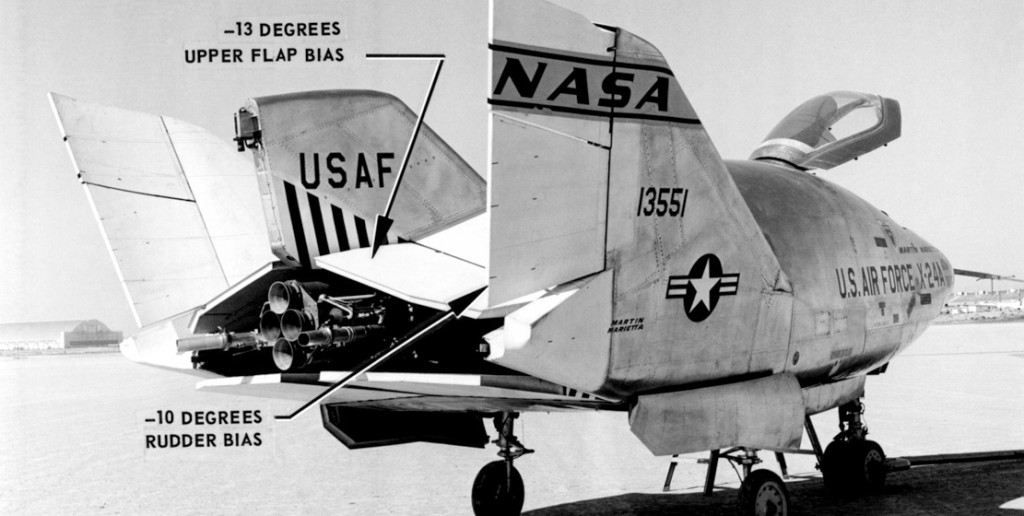
Eight aft-mounted moveable surfaces were used for flight control — two upper and two lower body flaps (one pair on either side of the fixed central fin, serving as both elevator and ailerons), and a two-segment split rudder on each outboard fin. The body flaps provided both pitch and roll control via symmetrical and differential deflection. The upper flaps were usually biased to open up to 40 degrees above Mach 0.6, while the lower flaps moved in response to control inputs. Both flaps on each side were connected together by a clapper linkage so any control inputs that caused a lower flap to close completely were transmitted to the upper flap. The rudders operated both in a bias mode, to adjust vehicle stability for different flight conditions, and as conventional rudders for yaw control, using the upper surfaces only. The rudders were normally flared outward 2 degrees at transonic and supersonic speeds, and inward 10 degrees below about Mach 0.6. The body flaps and rudders were interconnected so the pilot’s lateral stick motions caused the upper rudders to deflect in proportion to the commanded aileron deflection. This improved the vehicle’s roll characteristics and reduced a lateral instability inherent in the design. The interconnect ratio (or KRA, as it was called) was programmed automatically as a function of Mach number and angle of attack, and could also be selected manually.
The flight controls were operated by two independent hydraulic systems, each with a low-pressure (2.750 psi) and high-pressure (3.000 psi) pump. All electrical power was provided by high-rate silver-zinc batteries. In case of primary electrical system failure, the hydraulic pumps could draw power from the separate flight test instrumentation system battery. A Sperry Gyroscope Company three-axis, triple-redundant Stability Augmentation System (SAS) featured cockpit-selectable pitch, yaw, and roll rate feedback gains, so different amounts of damping could easily be evaluated in flight. A similar system was later installed in the M2-F3, replacing the original, less-flexible Northrop Nortronics SAS.
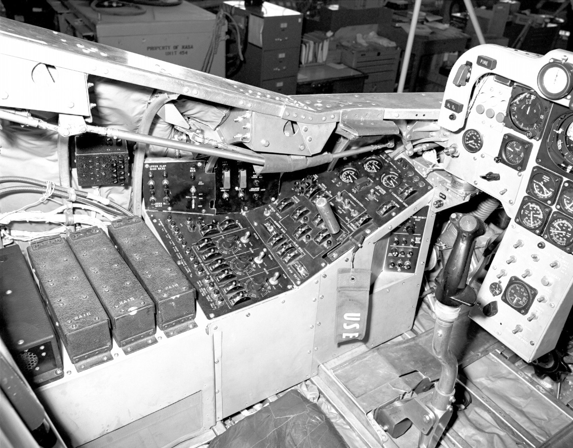
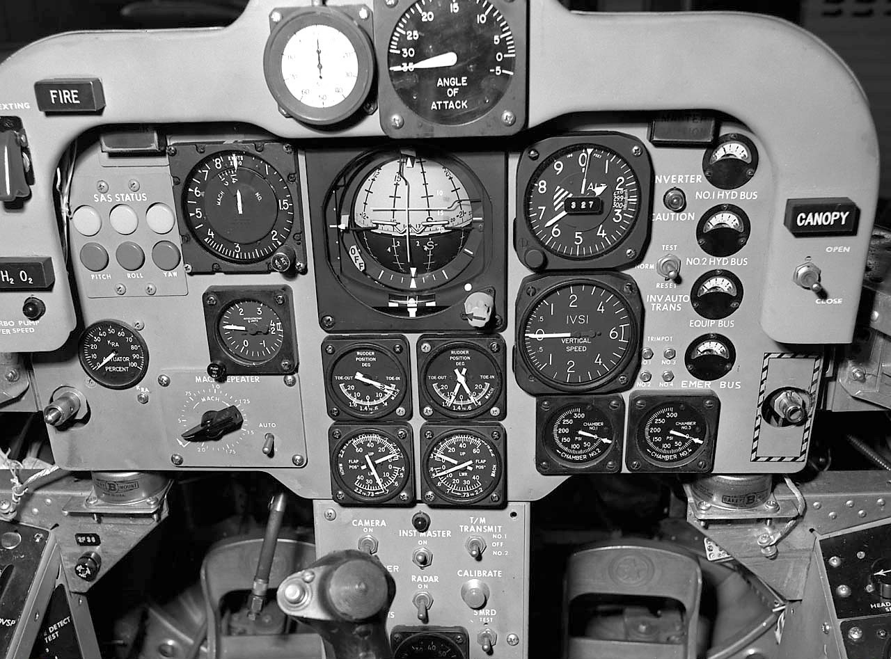
The cockpit was quite simple for a high-performance experimental aircraft. It contained basically conventional instrumentation with stick and rudder pedal/brake controls. The stick, through the KRA interconnect, controlled the upper rudders as well as the body flaps, but since the interconnect was automatic the piloting techniques were standard and no special controls were needed. The instrument panel was dominated by a large central three-axis attitude indicator which showed pitch, roll, and heading angles, and also included a sideslip indicator, a backup angle of attack bar and a pitch angle null index. Other main panel instruments were an airspeed/Mach-meter, altimeter, angle of attack meter, engine burn time clock, and control surface bias and differential position indicators. Four tiny meters on the right side of the main panel displayed electrical system parameters. The cockpit was pressurized to 3.5 psi.
Flight Test Program
The Air Force officially accepted the X-24A (tail number 66-13551) on August 3, 1967. It was delivered to Edwards three weeks later, but some 20 months would pass before it took to the air. Prior to being cleared for flight, the aircraft endured a busy schedule of ground tests, wind tunnel runs and systems evaluations. Four months of ground checkouts and static tests began on October 5, followed by full-scale testing in Ames’ 40-by-80-foot wind tunnel in February and March 1968. Then came low and high-speed taxi tests, using the landing rockets for propulsion, to check out ground handling performance. After an NB-52/X-24A mated taxi test on April 2. 1969, and a captive flight on April 4, the first free flight was finally scheduled for two weeks later. By that time, the X-1·5 program, having priority on use of the carrier aircraft, had drawn to a close after 199 flights, so the X-24A only had to compete with the HL-10 for NB-52 test support time.
The objectives of the X-24A flight test program — funded by the Air Force with NASA operational management — were similar to those for the M2-F2 and HL-10. The X-24A Advanced Development Plan emphasized collection of aerodynamic stability and control data over flight regimes from low-supersonic to landing speeds. Energy management techniques for a medium L/D lifting body, flare and touchdown procedures and pilot workloads would also be investigated. It was hoped that the test results would furnish realistic design and performance criteria for future lifting bodies (including manned reentry vehicles, if the Air Force got its way). Early test plans called for 20 flights, with the X-24A ultimately reaching Mach 2 and an altitude of 100,000 feet. But even before rollout the Air Force ran into money problems, due in large part to Vietnam expenditures, and had to clamp a $3.5-million bUdget lid on the X-24A program. This money, combined with a “sizable” Martin investment, eventually bought a total of 28 flights with somewhat more modest objectives. The original altitude and Mach number goals were never reached.
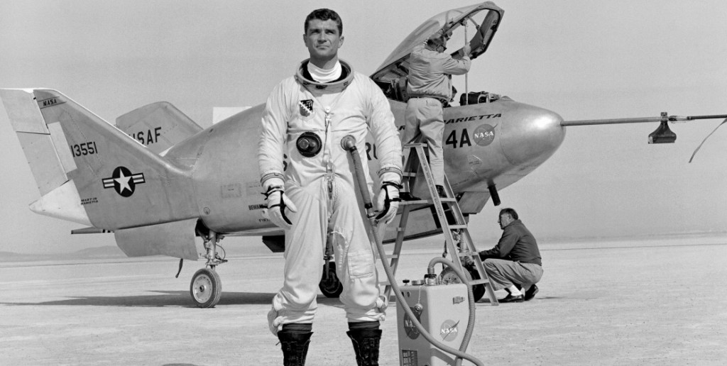
On April 17, 1969, Major Jerauld Gentry strapped himself into the graceful aluminum arrowhead suspended beneath the massive wing of NB-52 tail number 52-008. Thirty minutes later, the big mother ship with its diminutive cargo thundered aloft and climbed to an altitude of 45,000 feet for the program’s first glide flight. Five minutes before drop, as the bomber approached the launch point, Gentry transferred his power, cockpit pressurization and breathing oxygen from the NB-52 to X-24A systems. He checked the controls one last time. Everything was ready. On command, the X-24A dropped away smoothly and cleanly. The Lockheed F-1 04 chase planes tucked into formation with the bulbous silver craft as it started down. During the three-minute 37.4-second descent to Rogers Dry Lake, Gentry felt out the X-24A’s handling characteristics and stability. An amber SAS yaw warning light came on at one point, but he reset it and it stayed out. The flight went well until the landing approach.
Like the other lifting bodies, the X-24A landed hot and fast. The approach procedure called for the pilot to first nose over when still several thousand feet above the ground to increase his airspeed to about 300 knots. At 1,000 feet altitude, he would flare out for landing, reducing the rate of descent at touchdown to about 600 feet per minute from a pre-flare 13,500 feet per minute (compared with 500 to 700 feet per minute for a standard instrument approach in a normal aircraft). The landing gear was not lowered until the aircraft was down to 25 feet, hurtling across the desert nose-high in a horizontal glide. Bruce Peterson described the final approach and landing of a lifting body as like “landing at the bottom of a 30-degree dive-bombing run.”
On this first glide flight, a control system electrical malfunction popped a circuit breaker and locked in an incorrect KRA setting for approach. The mismatched interconnect ratio aggravated the subsequent landing difficulties. Rolling out of the turn onto final, Gentry felt an uncomfortable lateral oscillation start to build up as he pushed over to pick up airspeed for the pre-flare. He had previously experienced mild levels of the M2-F2’s nasty inclination to oscillate badly during approach (a tendency that had contributed to Peterson’s accident), so he had developed a sensitivity to that type of behavior. Reacting instinctively, he quickly pulled up the X-24A’s nose, bleeding off airspeed to 270 knots and, as he later recalled, “1 decided to use landing rockets at about that time.” In a swirling cloud of dust and a plume of superheated steam from the rockets, the X-24A touched down and rolled across the lakebed to a stop.
Gentry piloted the first five glide flights. Despite adjustments to the flight control system, the otherwise-smooth second and third flights were still marred by lateral oscillations on the approach, and both times he had to fire the landing rockets. A thorough investigation finally showed that a lot of the problem was due to pilot perception of the aircraft’s normal response to turbulence. There was nearly always some choppy air near the ground, especially in the summer months, and the X-24A exhibited an unusual rocking motion in light turbulence that was “not like flying through turbulence in any other airplanes I have ever flown,” to quote one of the pilots. Once the condition was recognized, there were no further approach problems and the landing rockets were not used again. NASA’s John Manke, who joined the program after putting in considerable time testing the HL-10, was next to fly the X-24A. After two frustrating attempts, one aborted due to clouds on October 15 and one cancelled because of rain on October 21, Manke flew the X-24A for the first time on October 22,1969. Three more glide flights with Gentry at the controls took place on November 13 and 25, 1969, and February 24, 1970. The last of these tested a new nose gear door designed to reduce a pronounced longitudinal trim change· with gear extension that had shown up on the first eight flights. Meanwhile, the XLR-11 engine was fired for the first time in the aircraft during a ground checkout on January 23.
The X-24A’s first powered flight was made on March 19, 1970, the tenth flight of the program. Gentry dropped from the NB-52 at 40,000 feet and seconds later lit two chambers of the XLR-11.
Again the lifting body had a surprise in store for the pilot. When the rocket engine fired, the nose pitched up abruptly and unexpectedly, and for a moment Gentry had his hands full trying to keep on the planned flight profile. The pitch-up, caused by an unpredicted plume, was not severe enough to jeopardize the flight, which other than that was textbook-perfect. Gentry attained an airspeed of 496 knots (Mach .87) and an altitude of 44,384 feet. He touched down on the lakebed seven minutes and four-seconds after launch. The only casualty of the flight was the left main gear tire, which got worn so badly on landing that it had to be replaced. Over the next four powered flights, the control system was tweaked to compensate for the pitch-up. The adjustments involved increasing the lower body flap bias travel limits.
Beginning with engine ignition just after release from the NB-52, a normal powered flight followed a well-defined profile with six phases — rotation, climb, pushover, glide, approach and landing. The rotation phase was flown at a constant angle of attack to get the planned climb angle. During the climb, the X-24A was typically pitched nose-up about 40 degrees and climbing at Mach .8 to .9. Then came the pushover phase, like going over the top of a roller coaster, and flown as a low angle of attack. On supersonic flights, the aircraft continued to accelerate through Mach 1 after pushover. At engine shutdown, the glide phase started. During this phase, preplanned maneuvers were performed to gather data, which was telemetered to the ground and recorded. The approach phase involved resetting flap and rudder biases for low-speed flight, and a 180-degree descending turn onto final. The flight ended with the flare to level flight, gear extension and touchdown on the lakebed.
The test pilots practiced flight profiles for long hours in a sophisticated cockpit simulator, and flew landing approaches in NASA F-104s, “dirty” with flaps and wheels down and engines throttled back to match the X-24A’s glide ratio. Preflight preparations frequently included over twenty hours of simulator time and as many as sixty F-1 04 approaches. Each flight plan included several alternate profiles which the pilot could fly if problems prevented him from carrying out the primary profile. Alternate profiles were flown five times in 18 powered flights.
The airspeed and altitude envelope was expanded gradually over the next six flights, and by late August of 1970 the X-24A had reached Mach .99 and 63,947 feet. The objective of the next flight, the 17th of the program, was to go supersonic for the first time. The flight plan called for a four-chamber rotation to a pitch angle of 35 degrees, climb to 50,000 feet, pushover to ten degrees angle of attack, and acceleration to Mach 1.1. Major Gentry was the pilot, and the flight was scheduled for August 26.
Things got off to a bad start when the XLR-11 refused to cooperate. Chambers 2 and 4 initially started, but a defective pressure switch erroneously signaled that number 4 chamber pressure was not rising properly, so that chamber was automatically shut down. Two attempts to light chambers 1 and 3 failed. In the meantime, Gentry inadvertently shut down chamber 2, the only one burning. Number 4 never did light, and number 2 would not relight because an auto-shutdown interlock was not cleared. Finally, Gentry managed to start chambers 1 and 3 on his third attempt, so he was able to fly one 01the alternate two-chamber flight profiles, peaking out at a Mach number of only .69 during the eight-minute flight.
[hr4][hr4]
Ground crewmen inspecting the aircraft after landing noticed fire damage at the aft end around the engine. This was the first indication anyone had that an in-flight fire had occurred. In addition to scorched paint, burned-through wires, melted hose clamps and severed aluminum tubing on the rocket engine itself, all four body flaps were buckled and distorted, and the upper-left flap had holes burned through the skin. The Air Force and NASA promptly set up an investigating committee to determine what had started the fire. In due time the committee concluded that the fire most likely was caused by propellant jettison combined with the shutdown characteristics of the XLR-11 engine. Propellant jettison was a straightforward procedure that had been followed on all of the previous powered flights. Any WALC and LOX remaining in the main tanks after engine shutdown was jettisoned before landing, both to reduce the landing weight and to minimize the chances of fire if there was a problem on landing. The propellants were dumped overboard through tubes running on either side of the engine combustion chambers. On this flight, LOX jettison had started 9.6 seconds after shutdown and WALC jettison 0.6 seconds later. Now the engine shutdown characteristics entered the picture. The XLR-11’s design permitted WALC to continue to flow into the chambers after shutdown because the WALC feed lines were longer downstream of the shutoff valves than the LOX lines. The excess WALC would usually burn with atmospheric oxygen in persistent “after-fires.” During ground engine runs, personnel were stationed near the engine with equipment to extinguish the after-fires, which could burn for quite some time if left unattended. On this flight the jettisoning propellants were apparently sucked into the X-24A’s base area by the turbulent wake, where they contacted either the after-fires burning in chambers 1 and 3, or the hot nozzle extensions. The resulting fire ruptured an aluminum 50-psi gaseous oxygen line, releasing pure oxygen to feed the fire. This brief, intense flareup, lasting about 20 seconds, caused most the of damage.
The committee’s report contained the disturbing conjecture that similar fires possibly occurred on many if not all of the previous X-24A powered flights, but they had not been severe enough to cause noticeable damage. It also noted that the two lifting bodies had “submerged” engine installations instead of the X-24A’s “open” design, and so were not susceptible to engine damage even if the jettisoning propellants did ignite. To prevent future fires, the time delay between engine shutdown and propellant jettison was increased to 20 seconds, and much of the aluminum tubing around the engine was replaced with stainless steel. The committee also recommended that the jettison tubes be moved further outboard away from the engine, but this suggestion was deferred because it would have required major structural modifications. The investigation and fixes kept the X-24A grounded for almost seven weeks.
The next flight, on October 14, 1970, saw the aircraft attain supersonic speed — Mach 1.19 — for the first time. The pilot was John Manke, and everything went smoothly for the six-minute 51-second flight, which reached a peak altitude of 67,900 feet. The flight had originally been scheduled for October 13, but when the X-24A was attached to its pylon, the NB-52s wing settled slightly under the weight and lowered the lifting body right down onto a ground servicing cart that someone had left in the wrong place. The small hole punched in the X-24A’s skin was patched, but the flight was delayed one day.
Three more supersonic flights followed between October 27, 1970, and January 21, 1971. The program’s highest altitude, 71,407 feet, was reached on the first, and a Mach number of 1.37 on the second. A failed angle-of-attack gauge on the third forced Manke to fly an alternate profile to Mach 1.02. Then, on February 4, came the only glide flight since powered flights had started, to check out new program pilot Air Force Major Cecil Powell, who had no lifting body experience. After a Mach 1.5 flight by Manke on February 18, Powell made his first powered flight on March 8, reaching a speed of just over Mach 1. On March 29, Manke, in the X-24A’s 25th flight, reached the highest speed of the program, Mach 1.60.
There were also frustrations. Engine problems on the last two flights made it impossible for Manke to accomplish the primary objectives. Chamber 3 would not light during the 27th flight on May 25, so he flew an alternate three-chamber profile, reaching Mach 1.2. The 28th and last flight took place on June 4, 1971. This time both chambers 3 and 4 refused to light, so the X-24A program ended with an unplanned subsonic (Mach .82) two-chamber alternate flight profile. Although the program ended on a slightly sour note, the bad luck on the last two flights was offset by ambitious plans the Air Force had for the aircraft, plans that did not involve either a distinguished retirement or the scrap heap.
Legacy and Aftermath
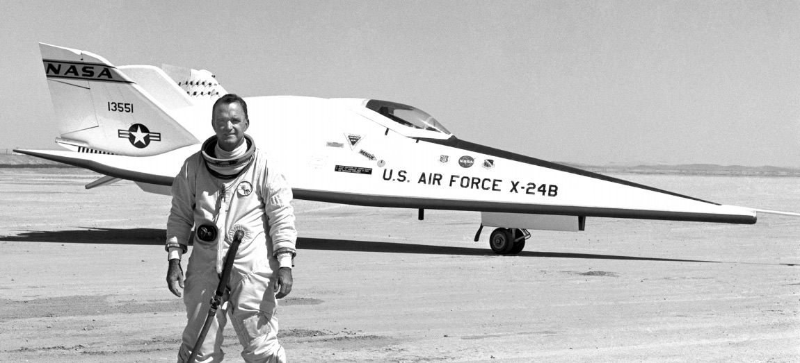
On July 29,1971, the Air Force announced that the X-24A would be returned to Martin Marietta and rebuilt into the higher-performance X-24B. The “B,” based on a Flight Dynamics Laboratory design called the FDL-8, featured the defunct Dyna-Soar’s long, pointed nose mated to the X-24A and stub horizontal tail surfaces. The Air Force had considered building the FDL-8 since 1968, and originally planned to adapt one of the SV-5Js. However, using the X-24A meant fewer, less expensive modifications — it already had a rocket engine, propellant tanks and plumbing, and a rocket-plane cockpit. At Martin’s Denver plant, the new shape was grafted onto the basic X-24A airframe with minimum changes to the underlying structure. Most of the internal systems remained the same.
The X-24B flew 36 times from August 1, 1973, through November 26,1975. It racked up a number of distinctions during a highly successful flight test program, including the first landing by a lifting body on Edwards’ 15,OOO-foot concrete main runway rather than the lakebed (directly proving the technique later used by the Space Shuttle), and the last rocket-powered flight by an X-series research aircraft, on September 23, 1975, by NASA’s former X-15 pilot William H. Dana.
Despite Air Force hopes to the contrary, the X-24A did not turn out to be the prototype of a military manned spacecraft, and when he M2-F3, HL-10 and X-24B programs were wrapped up, there were no further plans for future lifting bodies. The Space Shuttle was being designed while the lifting bodies were flying, and NASA elected to go with a more conventional double-delta wing for the Orbiter rather than take the more-risky lifting-body approach. But the lifting bodies did contribute to the Shuttle program. They showed that the Shuttle would not need auxiliary jet engines for approach and landing. The weight saved by not having to haul jet engines into orbit and back translated into a healthy increase in cargo capacity. They also proved out high-energy dead-stick approach and landing techniques. And the X-24A, in a series of tests in late 1969, confirmed the feasibility of Shuttle instrument approaches with ceilings as low as 500 to 1,000 feet. The strange, wingless vehicles were far more than aeronautical curiosities. They played an important role in making access to space routine.
The X-24B is on display at the Air Force Museum, Wright-Patterson Air Force Base, Dayton, Ohio, alongside the recovered NO.3 SV-5D PRIME reentry vehicle and one of the unflown SV-5Js, modified and painted to look like the X-24A. The other SV-5J is at the Air Force Academy, Colorado Springs, Colorado.


